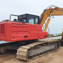
Performing a transmission fluid pressure test on a Takeuchi TB1140 Hydraulic Excavator involves several steps and tools. click here for more details on the download manual…..
- Amazing Repairing of Excavator Hyduralic Main Assembly | Rebuilding Hyduralic Assembly | Amazing Repairing of Caterpillar Diesel Pump | Diesel Pump Repairing | Caterpillar Diesel Pump.
Below are the detailed descriptions of each tool and the procedure:
### Tools Required:
– **Pressure Gauge**:
– A hydraulic pressure gauge suitable for measuring the transmission fluid pressure. It should have a range that covers the expected pressure values for the TB1140.
– **Adapting Fittings**:
– Various fittings to connect the pressure gauge to the hydraulic system. This may include NPT fittings, hoses, and quick-connect couplers that are compatible with the excavator’s hydraulic ports.
– **Wrenches**:
– A set of metric and standard wrenches for loosening and tightening fittings. These are necessary for safely attaching the pressure gauge without leakage.
– **Fluid Catch Pan**:
– A pan to catch any hydraulic fluid that may spill during the process. This helps maintain a clean workspace and prevents slipping hazards.
– **Shop Towels or Rags**:
– For cleaning up any spills and wiping down fittings and connections to avoid contamination of the hydraulic system.
– **Safety Gear**:
– Safety glasses, gloves, and possibly a face shield to protect against hydraulic fluid splashes and other potential hazards.
### Procedure:
– **Preparation**:
– Ensure the excavator is parked on a level surface and is turned off. Engage the parking brake and remove the key to prevent accidental start-up during testing.
– **Identify Testing Ports**:
– Locate the transmission fluid pressure test ports as specified in the Takeuchi TB1140 service manual. These ports are usually located on or near the hydraulic transmission unit.
– **Connect Pressure Gauge**:
– Using the appropriate adapting fittings, connect the pressure gauge to the identified test port. Ensure all connections are tight to avoid leaks. If necessary, use thread sealant to prevent hydraulic fluid from escaping.
– **Prepare for Testing**:
– Place the fluid catch pan under the connection point to catch any hydraulic fluid that may leak during the procedure.
– **Start the Excavator**:
– With the gauge connected and the area clear, start the excavator’s engine. Allow it to reach operating temperature, as fluid pressure may vary with temperature.
– **Check Pressure Readings**:
– Observe the pressure readings on the gauge while engaging different hydraulic functions (e.g., boom raise/lower, swing, and bucket operations). Note the pressure readings for each function and compare them to the specifications found in the service manual.
– **Record Data**:
– Document the pressure readings for each hydraulic function tested. This data is critical for diagnosing potential issues within the hydraulic system.
– **Shut Down the Engine**:
– Once testing is complete, turn off the engine and allow it to cool down if necessary.
– **Disconnect Pressure Gauge**:
– Carefully disconnect the pressure gauge from the test port. Be prepared for any residual fluid to escape. Ensure any spilled fluid is cleaned up using shop towels or rags.
– **Reinstall any Removed Parts**:
– If any fittings or covers were removed to access the test ports, reinstall them securely to avoid future leaks.
– **Inspect for Leaks**:
– After the test, inspect all connections and fittings for leaks, ensuring the hydraulic system is sealed properly.
– **Dispose of Fluid Properly**:
– If any hydraulic fluid was caught in the fluid catch pan, dispose of it according to local regulations regarding hazardous materials.
Following these steps will ensure a safe and effective transmission fluid pressure test on a Takeuchi TB1140 Hydraulic Excavator, helping you diagnose any hydraulic system issues accurately. Always refer to the specific service manual for the TB1140 for any additional procedures or specifications.
The brake hose is a critical component in a vehicle’s braking system, serving as a flexible conduit that transmits brake fluid from the master cylinder to the brake calipers or wheel cylinders. Typically made from a combination of rubber and reinforced materials, such as nylon or steel braiding, brake hoses are designed to withstand high pressure and provide durability under various environmental conditions.
When the driver applies pressure to the brake pedal, the master cylinder generates hydraulic pressure that travels through the brake hoses. This pressure activates the brake calipers or wheel cylinders, which in turn clamp down on the brake pads and rotors or expand the brake shoes against the drum, effectively slowing down or stopping the vehicle. The flexibility of the brake hose allows for movement and suspension travel, accommodating the vehicle’s dynamics while ensuring a reliable connection for fluid transfer.
Brake hoses are engineered to be resistant to heat, abrasion, and chemical exposure, as they are often subjected to harsh conditions. Regular inspection of brake hoses is essential for vehicle safety, as wear, cracking, or bulging can lead to brake failure or fluid leaks. Manufacturers recommend replacing brake hoses every few years or as part of routine maintenance to ensure optimal performance and safety. Overall, the brake hose is an integral part of the hydraulic braking system, playing a vital role in the effective and safe operation of a vehicle.