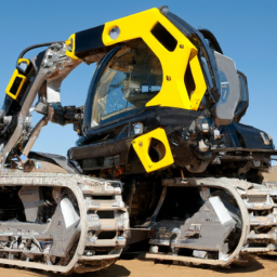
Replacing the ignition coil on a JCB 190 190HF Robot involves several steps and requires certain tools. click here for more details on the download manual…..
- Мини погрузчики с бортовым поворотом JCB POWER BOOM Мини-погрузчики с бортовым поворотом JCB нового поколения являются самыми безопасными в мире. Несмотря на …
Below are the detailed instructions and tools you’ll need for the process.
### Tools Required:
– **Socket Set**: A complete metric socket set (usually 8mm to 19mm) for removing bolts and nuts.
– **Torque Wrench**: To ensure bolts are tightened to the manufacturer’s specifications.
– **Screwdriver Set**: Both flathead and Phillips screwdrivers for removing covers and securing components.
– **Pliers**: To grip and manipulate wires and small components.
– **Wire Cutters/Strippers**: For any necessary modifications to wiring if connectors need replacement.
– **Multimeter**: To test the electrical connections and ensure the new coil is functioning properly.
– **Safety Gear**: Gloves and safety glasses to protect against debris and electrical hazards.
– **Clean Rag or shop Towels**: For cleaning and wiping down components during the process.
– **Service Manual**: A JCB service manual for reference on specifications and diagrams.
### Replacement Procedure:
– **Ensure Safety**:
– Disconnect the battery by removing the negative terminal to prevent any electrical shorts or shocks.
– Wear safety gloves and goggles to protect against any debris or electrical hazards.
– **Access the Ignition Coil**:
– Locate the ignition coil by referring to the service manual. It is typically found near the engine’s cylinder head.
– Remove any engine covers or components obstructing access to the ignition coil using the appropriate sockets or screwdrivers.
– **Disconnect the Wires**:
– Carefully disconnect the electrical connectors from the ignition coil. Use pliers if necessary, but be gentle to avoid damaging the connectors.
– Note the orientation and placement of the wires to ensure correct reconnection later.
– **Remove the Ignition Coil**:
– Unscrew the bolts or screws securing the ignition coil in place using the socket set or screwdriver. Keep these fasteners safe for reinstallation.
– Gently pull the ignition coil away from the engine. If it’s stuck, wiggle it slightly to break the seal but avoid excessive force.
– **Install the New Ignition Coil**:
– Take the new ignition coil out of its packaging, and compare it with the old one to ensure it is the correct part.
– Position the new ignition coil in place, aligning it with the mounting holes.
– **Secure the Ignition Coil**:
– Reinstall the bolts or screws to secure the new ignition coil. Use the torque wrench to tighten them to the manufacturer’s specifications as noted in the service manual.
– **Reconnect the Wires**:
– Reattach the electrical connectors to the new ignition coil, ensuring they are secured and connected in the correct order as noted during disassembly.
– **Reassemble Any Removed Components**:
– Replace any engine covers or components that were removed to access the ignition coil. Ensure all fasteners are tightened securely.
– **Reconnect the Battery**:
– Reattach the negative terminal of the battery, ensuring it is tight and secure.
– **Testing**:
– Start the engine to ensure it runs smoothly. If available, use a multimeter to test the new ignition coil and ensure proper voltage is being delivered.
– check for any engine warning lights or error codes, and troubleshoot if necessary.
– **Final Inspection**:
– After confirming proper operation, do a final visual inspection to ensure all tools are removed from the work area and all components are securely fastened.
### Final Notes:
– Always refer to the JCB service manual for specific torque settings and detailed diagrams.
– Make sure to dispose of the old ignition coil and any other waste materials in accordance with local regulations.
– If you encounter any issues during the process, consult a professional mechanic for assistance.
A brake drum is a crucial component of a vehicle’s braking system, primarily found in older cars and some light trucks. It serves as a cylindrical structure that houses the brake shoes and is integral to the drum brake system, which operates on the principle of friction to slow down or stop the vehicle. When the driver presses the brake pedal, hydraulic pressure is transmitted through the brake lines to the brake shoes, which then expand outward against the inner surface of the brake drum. This friction generated between the shoes and the drum creates the necessary stopping force.
Typically made from cast iron or aluminum, brake drums are designed to withstand high temperatures and stresses generated during braking. Over time, however, they can wear down or become warped due to prolonged use and excessive heat buildup, leading to reduced braking efficiency and potentially compromising safety. Maintenance of brake drums often includes periodic inspection for signs of wear, such as scoring or cracking, and replacement as necessary.
The advantage of drum brakes includes their ability to provide strong stopping power, especially in vehicles with heavier loads. However, they tend to be less effective in dissipating heat compared to disc brakes, which is why many modern vehicles utilize disc brakes in combination with or instead of drum brakes. Overall, the brake drum is a vital part of the braking mechanism, playing a significant role in vehicle safety and control.